This appendix begins by providing a general overview of model compilers (sometimes referred to as the software architecture) followed by a brief description of the major components of MC-3020. Next, a more detailed look is taken at the two types of tasks found in the MC-3020 architecture and how they interact. Finally, the general operational nature of each task type is described. The intent is to provide the reader with a complete, high level view of the MC-3020 architecture, sufficient to provide a context for the rest of this manual.
This section provides a general overview of how model compilers fit into the Shlaer-Mellor method.
The Shlaer-Mellor approach to software development begins by partitioning the system into separate subject matters referred to as domains. Each domain is then analyzed using xtUML modeling and finally the system is implemented by translating the xtUML models into the chosen implementation technology (e.g. language, operating system, custom hardware) using the model compiler.
The software architecture is that domain which deals with the subject matter of designing and implementing the system. It abstracts the design and implementation patterns appropriate for the system and defines mapping rules between the xtUML models and these design and implementation patterns. This approach provides a uniform set of data, function, and control abstractions that are used system wide and forms the basis for translating the xtUML models based on an automation of the mapping rules.
A software architecture is made up of three main components: mechanisms, rule files (formerly archetypes) and marks. In addition, build and diagnostic components are provided to facilitate constructing and debugging the system. These components are described in the following subsections.
A mechanism is architecture functionality that is specified, designed, coded, and compiled to work with all xtUML models. It is not customized on an xtUML element boundary. Examples of mechanisms in an object-oriented ANSI C model compiler include code for managing circular queues and modules written to perform set manipulation in a generic fashion.
In some architectures, pre-compiled mechanisms are not necessary. All code is generated from rule files or included in uncompiled source form. This is true of MC-3020.
MC-3020 is purely ANSI C and generates code that can be compiled by any compiler compliant with the ANSI standard. The core model compiler now uses no libraries or system functions at all. Generated code is pure native C. All string manipulation library functions (memcpy, strcpy, strcat and related) used in previous versions have been eliminated. Native C functions have replaced these system calls. This has been accomplished in such a way that a user can redefine the functions with a small rule file change or macro definition.
This change makes it simpler and easier to integrate with
compilers of various makes and models and manufacturers. In
addition, some simpler compilers will link in an entire library
of system functions when any single function is accessed from
the library. Only stdio.h remains as
exposure on this front.
stdio.h is included simply for convenience
during debug (for printf, etc). All generated
code is simple, native C. When integrating realized external
entities and timer services (TIM), other system libraries will
be necessary. However, the core xtUML generated code remains
simple ANSI C.
A rule file is a combination of an implementation pattern and translation rules for filling out that pattern based upon specifics of the xtUML models. Thus a rule file is designed to be customized on an xtUML element boundary. An example of a rule file in an object-oriented ANSI C model compiler is the code pattern for a struct that will be used to represent xtUML classes along with the translation rules for populating that code pattern with such xtUML elements as object name, attribute name, and valid events for that object.
When there is more than one software architecture element into which an xtUML element can be translated, marks (formerly "colors") are used to indicate which translation to make. The name ``mark'' comes from the visualization of using a highlighter pen to mark each element that has a particular property. Marks are used to direct the translation to select one of two or more branches in the translation rules. It is through marking that design decisions are injected during the translation process.
An example of the type of design information that is specified through marking is the mapping of analysis data types into implementation (e.g., C) data types. Clearly, this is information that does not belong in either the xtUML models or the model compiler itself. Such information is maintained outside the model compiler and models in marking tables that are accessed during the translation process.
In addition to the three basic components of a model compiler, the mechanisms, rule files, and marks, there are also two tools which come with an architecture to facilitate the translating and building of the system and provide some diagnostic capabilities for debugging the system. These are:
build tools
diagnostic tools
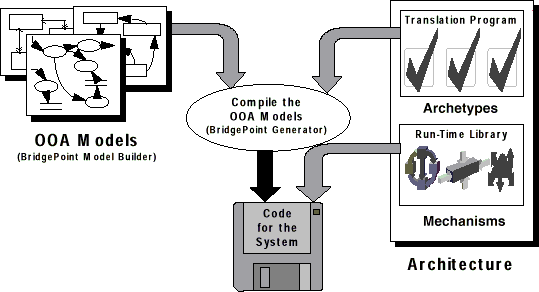
Just as assembly language is translated into machine code, and a high level language is translated into assembly code (which is then translated into machine code), the xtUML models and their translation into a high level language can be viewed as the next evolutionary step in language development. The xtUML models now become the new ``programming language'' and the software architecture the new ``compiler''. This approach is referred to as model based translative development (MBTD).
Applying this analogy to the model compiler components, the mechanisms represent the run-time library that comes with a conventional compiler to provide the functions necessary to successfully execute the compiled code in the chosen implementation environment. Likewise, the rule files represent the translation program or compiler that actually translates the high level source code input to assembly code output.
Figure B.1, “ Model Compiler Analogy with BridgePoint Tool Set” shows an overview of how the model compilation process works in the context of the BridgePoint tool set. The xtUML models are read from the repository of the BridgePoint Builder and the translation rule files are fed into the BridgePoint Generator.